位操作相关
寄存器读-改-写问题
问题描述
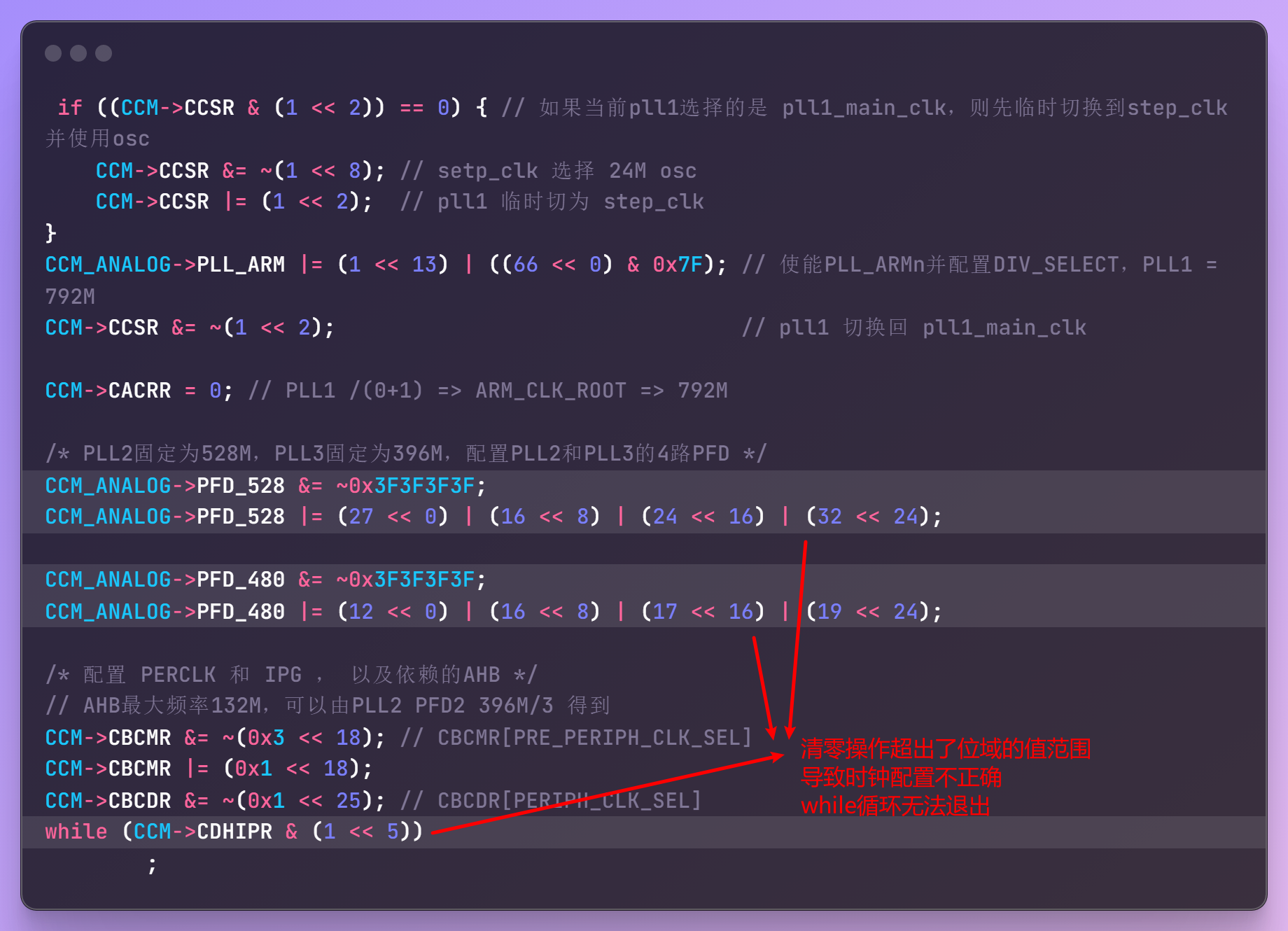
在学习STM32时,操作寄存器习惯于先清零再置位,一直没有遇到什么问题,这是因为STM32大部分寄存器的复位值为0,因此清零不会有任何副作用;但是在学习IMX6ULL时钟模块时,我延续该习惯配置PLL_PFD寄存器时却出现了令人困惑的异常。起初我的代码版本如下;

想在设置相关bit之前,将对应的bit先清零:

但我忽略了一个重要的信息:寄存器某些位域的值是有大小限制的:

因为这个细节,PFD时钟配置没有按照预期执行,导致时钟初始化while握手变成了死循环
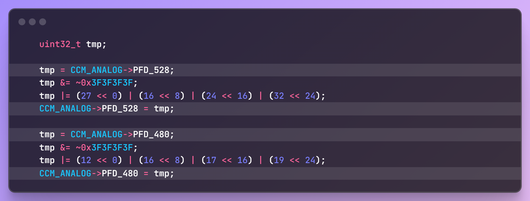
寄存器操作最佳实践:读-改-写
链接脚本相关
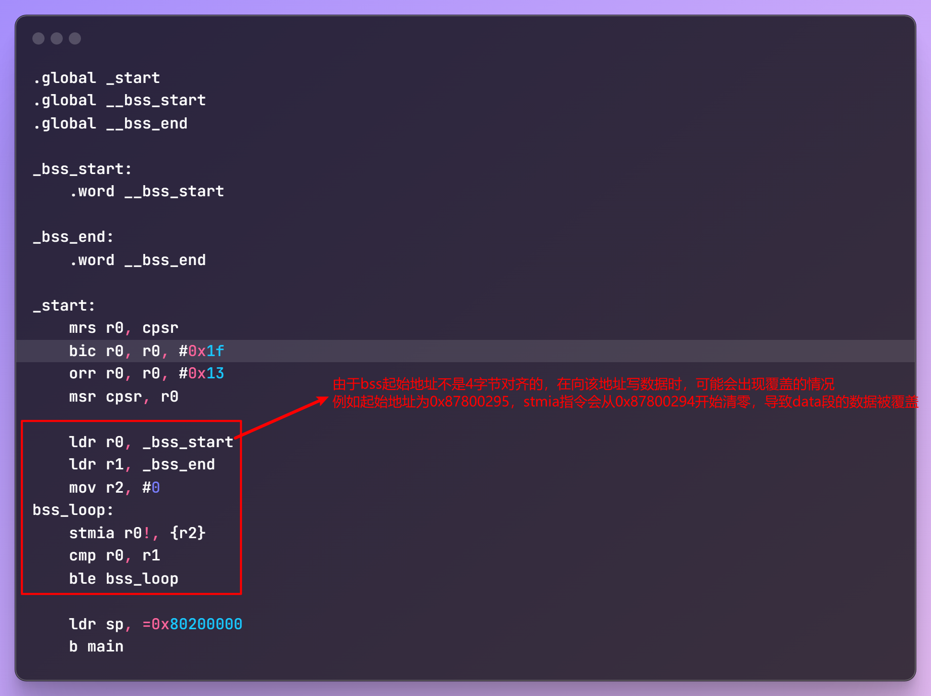
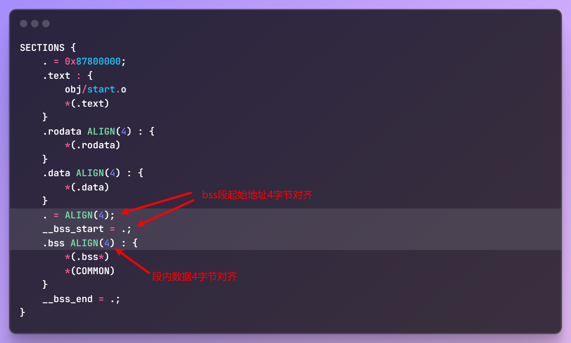
bss段起始/结束地址需要4字节对齐
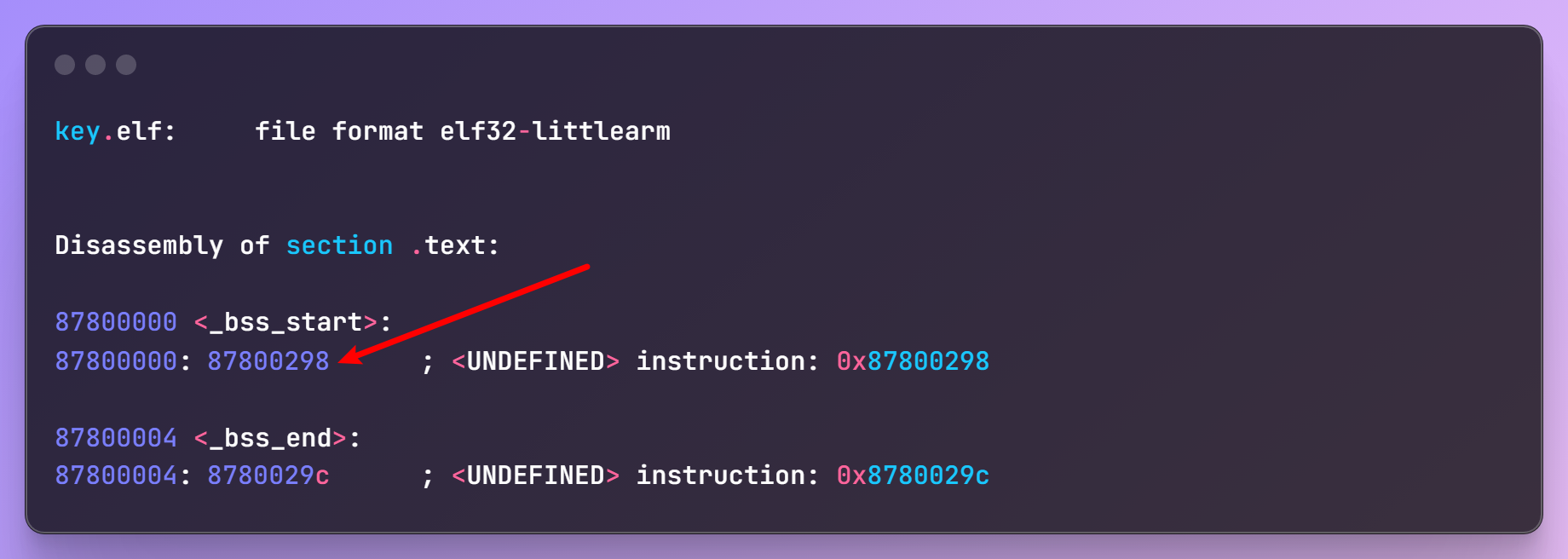
非4字节对齐可能会导致其他段的数据被覆盖
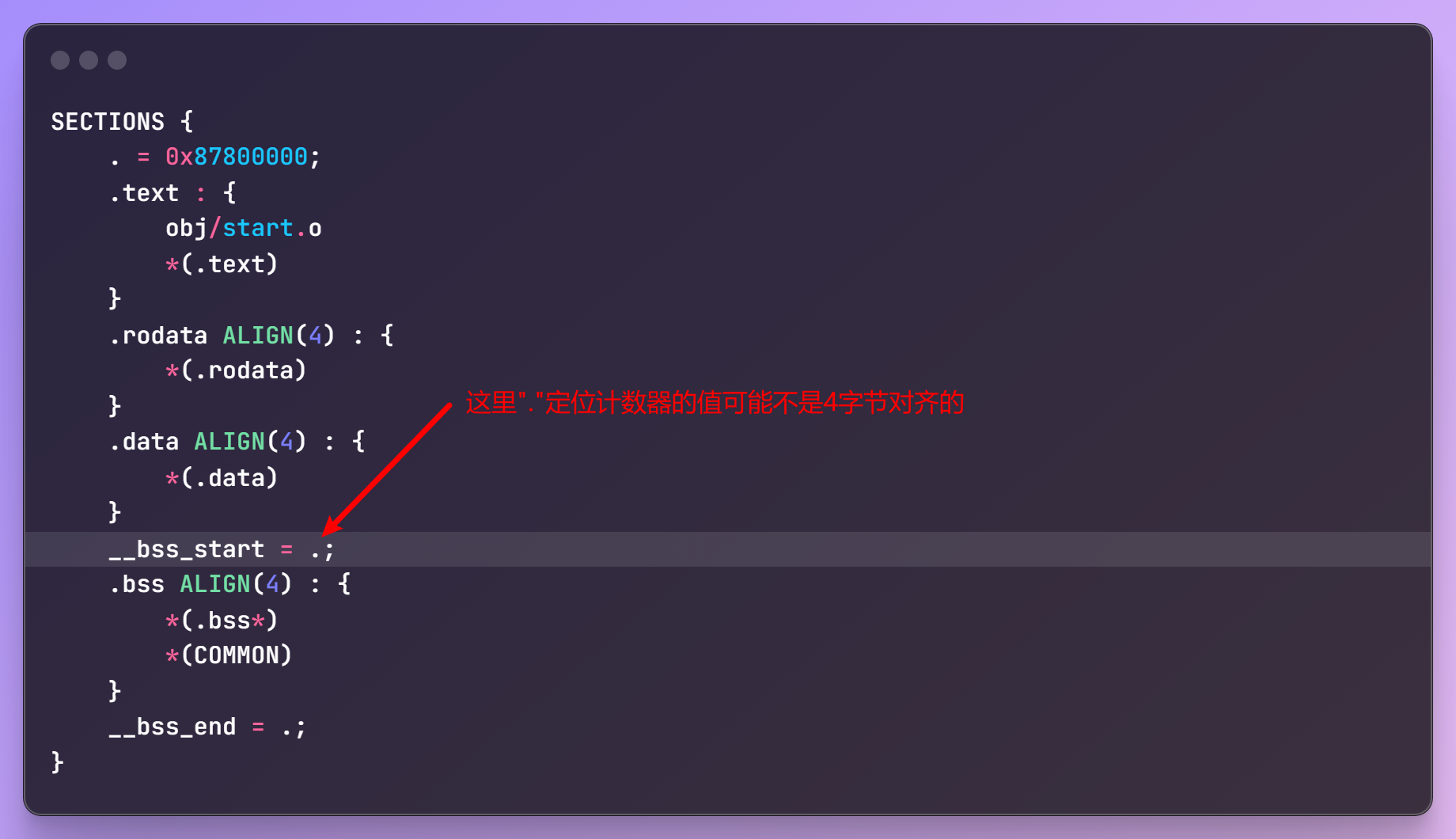
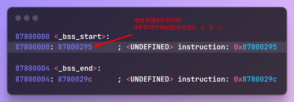
链接脚本指定4字节对齐
SOC外设相关
IOMUX
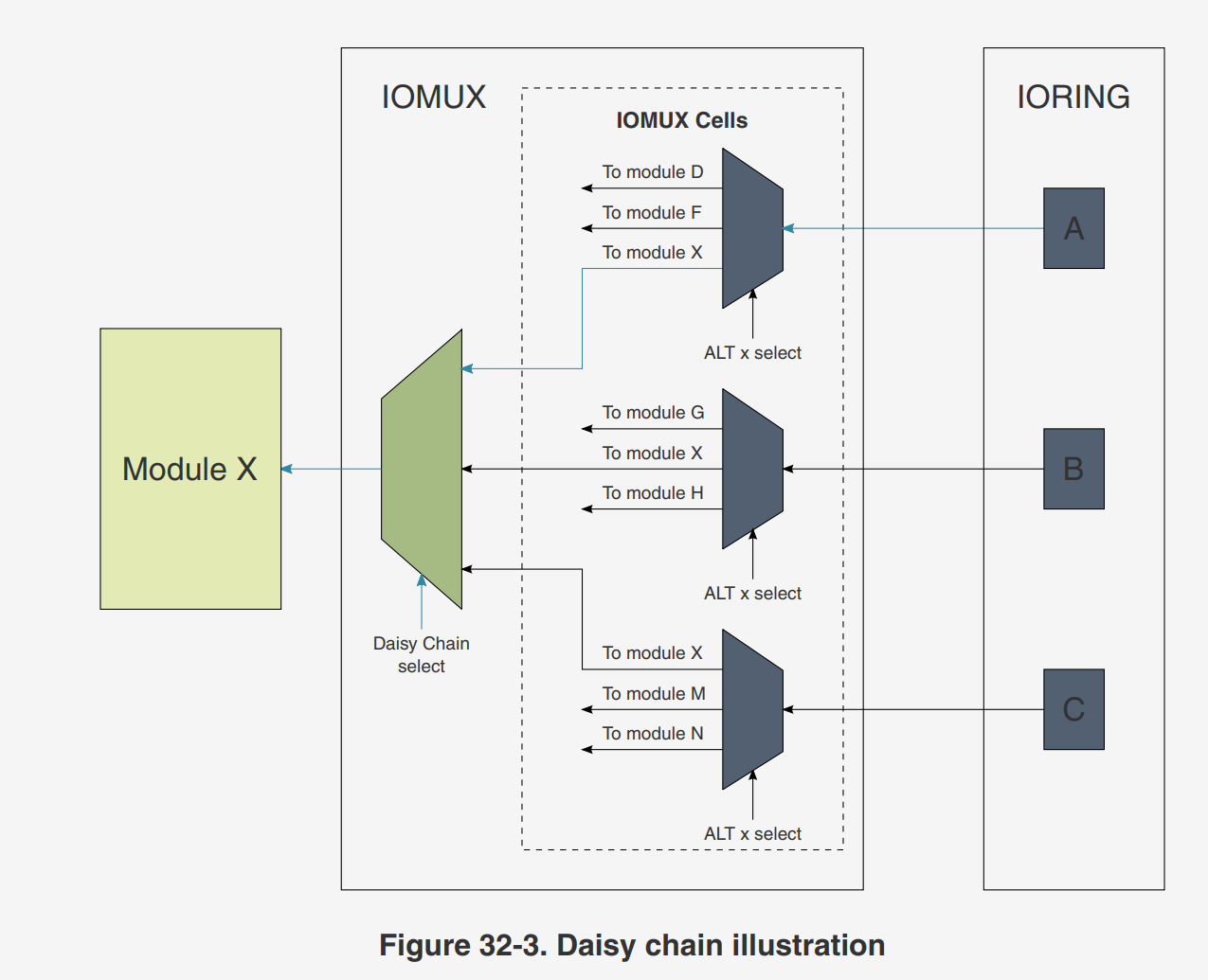
菊花链


回环输入


I2C
轮询方式I2C驱动
https://github.com/zanwen/imx6ull_bare_experiment/tree/main/16_i2c
driver_i2c.h
//
// Created by 86157 on 2025/1/10.
//

#ifndef INC_16_I2C_DRIVER_I2C_H
#define INC_16_I2C_DRIVER_I2C_H

#include "imx6ull.h"

#define DEV_ADDR 0x1E
void Driver_I2C_Init(I2C_Type *base);
void Driver_I2C_Start(I2C_Type *base);
void Driver_I2C_ReStart(I2C_Type *base);
void Driver_I2C_Stop(I2C_Type *base);
void Driver_I2C_SendAddr(I2C_Type *base, uint8_t addrRW);
void Driver_I2C_SendBytes(I2C_Type *base, uint8_t *data, uint8_t len);
void Driver_I2C_ReadBytesAndStop(I2C_Type *base, uint8_t *buf, uint8_t len);
void Driver_I2C_MasterWrite(I2C_Type *base, uint8_t addr, uint8_t regAddr,
                           uint8_t *data, uint8_t len);

void Driver_I2C_MasterRead(I2C_Type *base, uint8_t addr, uint8_t regAddr,
                           uint8_t *buf, uint8_t len);

void Driver_I2C_Test(void);

#endif//INC_16_I2C_DRIVER_I2C_H
driver_i2c.c
//
// see 31.5 Initialization
//
#include "driver_i2c.h"
#include "logger.h"
#include "driver_delay.h"
void Driver_I2C_WaitFlag(I2C_Type *base, uint8_t bitIndex, uint8_t bitValue);
void Driver_I2C_Init(I2C_Type *base) {
// I2C disable and reset
base->I2CR |= (1 << 7);
// SCL clock freq: 66M / 640 = 103.125kHz
base->IFDR = 0x15;
// I2C enable
base->I2CR |= (1 << 7);
}
void Driver_I2C_Start(I2C_Type *base) {
// wait for bus idle
Driver_I2C_WaitFlag(base, 5, 0);
// clear interrupt flag
base->I2SR &= ~(1 << 1);
// [5]: Changing MSTA from 0 to 1 signals a Start on the bus and selects Master mode.
base->I2CR &= ~(1 << 5);
base->I2CR |= (1 << 5);
}
void Driver_I2C_ReStart(I2C_Type *base) {
// clear interrupt flag
base->I2SR &= ~(1 << 1);
// [2]: Repeat start
base->I2CR |= (1 << 2);
}
void Driver_I2C_WaitFlag(I2C_Type *base, uint8_t bitIndex, uint8_t bitValue) {
uint16_t timeout = 0xFFFF;
while (timeout && ((base->I2SR >> bitIndex) & 0x01) != bitValue) {
timeout--;
}
if (timeout == 0) {
LOG_ERROR("wait flag timeout, bitIndex: %d, bitValue: %d", bitIndex, bitValue);
}
}
void Driver_I2C_Stop(I2C_Type *base) {
// clear interrupt flag
base->I2SR &= ~(1 << 1);
base->I2CR |= (1 << 5);
base->I2CR &= ~(1 << 5);
}
void Driver_I2C_SendAddr(I2C_Type *base, uint8_t addrRW) {
// select Transmit mode
base->I2CR |= (1 << 4);
// write DR
base->I2DR = addrRW;
// wait for transmit complete
Driver_I2C_WaitFlag(base, 1, 1);
// clear interrupt flag
base->I2SR &= ~(1 << 1);
}
void Driver_I2C_SendBytes(I2C_Type *base, uint8_t *data, uint8_t len) {
// select Transmit mode
base->I2CR |= (1 << 4);
for (uint8_t i = 0; i < len; ++i) {
// wait for transmit complete
base->I2DR = data[i];
// wait for transmit complete
Driver_I2C_WaitFlag(base, 1, 1);
// clear interrupt flag
base->I2SR &= ~(1 << 1);
}
}
void Driver_I2C_ReadBytesAndStop(I2C_Type *base, uint8_t *buf, uint8_t len) {
// select Receive mode; enable auto ack
base->I2CR &= ~((1 << 4) | (1 << 3));
//If Master Receive mode is required, then
//I2C_I2CR[MTX] should be toggled and a dummy read of the I2C_I2DR register must be
//executed to trigger receive data.
base->I2DR;// dummy read
// For a master receiver to terminate a data transfer, it must inform the slave transmitter by
// not acknowledging the last data byte. This is done by setting the transmit acknowledge
// bit (I2C_I2CR[TXAK]) before reading the next-to-last byte
// Before the last byte is read a Stop signal must be generated
base->I2CR &= ~(1 << 3); // auto ack
if (len == 1) {
// disable auto ack
base->I2CR |= (1 << 3);
Driver_I2C_WaitFlag(base, 1, 1);
// generate stop
base->I2CR &= ~(1 << 5);
buf[0] = base->I2DR;
} else {
for (uint8_t i = 0; i < len; ++i) {
// wait for transmit complete
Driver_I2C_WaitFlag(base, 1, 1);
if (i == len - 2) {
// disable auto ack 读倒数第二个字节之前
base->I2CR |= (1 << 3);
}
if(i == len - 1){
// generate stop 读最后一个字节之前
base->I2CR &= ~(1 << 5);
}
buf[i] = base->I2DR;
// clear interrupt flag
base->I2SR &= ~(1 << 1);
}
}
}
void Driver_I2C_MasterWrite(I2C_Type *base, uint8_t addr, uint8_t regAddr,
uint8_t *data, uint8_t len) {
Driver_I2C_Start(base);
Driver_I2C_SendAddr(base, addr << 1 | 0);
Driver_I2C_SendBytes(base, ®Addr, 1);
Driver_I2C_SendBytes(base, data, len);
Driver_I2C_Stop(base);
}
void Driver_I2C_MasterRead(I2C_Type *base, uint8_t addr, uint8_t regAddr,
uint8_t *buf, uint8_t len) {
Driver_I2C_Start(base);
// dummy write
Driver_I2C_SendAddr(base, addr << 1 | 0);
Driver_I2C_SendBytes(base, ®Addr, 1);
Driver_I2C_ReStart(base);
Driver_I2C_SendAddr(base, addr << 1 | 1);
Driver_I2C_ReadBytesAndStop(base, buf, len);
}
void Driver_I2C_Test(void) {
IOMUXC_SetPinMux(IOMUXC_UART4_TX_DATA_I2C1_SCL, 1);
IOMUXC_SetPinMux(IOMUXC_UART4_RX_DATA_I2C1_SDA, 1);
// 开漏
IOMUXC_SetPinConfig(IOMUXC_UART4_TX_DATA_I2C1_SCL, 0x18B0);
IOMUXC_SetPinConfig(IOMUXC_UART4_RX_DATA_I2C1_SDA, 0x18B0);
Driver_I2C_Init(I2C1);
uint8_t data = 0x04;
Driver_I2C_MasterWrite(I2C1, DEV_ADDR, 0x00, &data, 1);
Driver_Delay_MS(10);
data = 0x03;
Driver_I2C_MasterWrite(I2C1, DEV_ADDR, 0x00, &data, 1);
uint8_t buf[1] = {0};
Driver_I2C_MasterRead(I2C1, DEV_ADDR, 0x00, buf, 1);
LOG_DEBUG("buf = %#x", buf[0]);
LOG_DEBUG("Driver_I2C_Test done");
uint8_t alsData[2] = {0};
uint8_t psData[2] = {0};
uint16_t als = 0, ps = 0;
while(1) {
Driver_I2C_MasterRead(I2C1, DEV_ADDR, 0x0C, alsData, 2);
Driver_I2C_MasterRead(I2C1, DEV_ADDR, 0x0E, psData, 2);
als = (alsData[1] << 8) | alsData[0];
ps = ((psData[1] & 0x3F) << 4) | (psData[0] & 0xF);
LOG_DEBUG("als = %d, ps = %d", als, ps);
Driver_Delay_MS(500);
}
}
OV5640摄像头驱动
LCD
像素的位深(Bits per Pixel, bpp)


LCD数据总线宽度

字节大小端
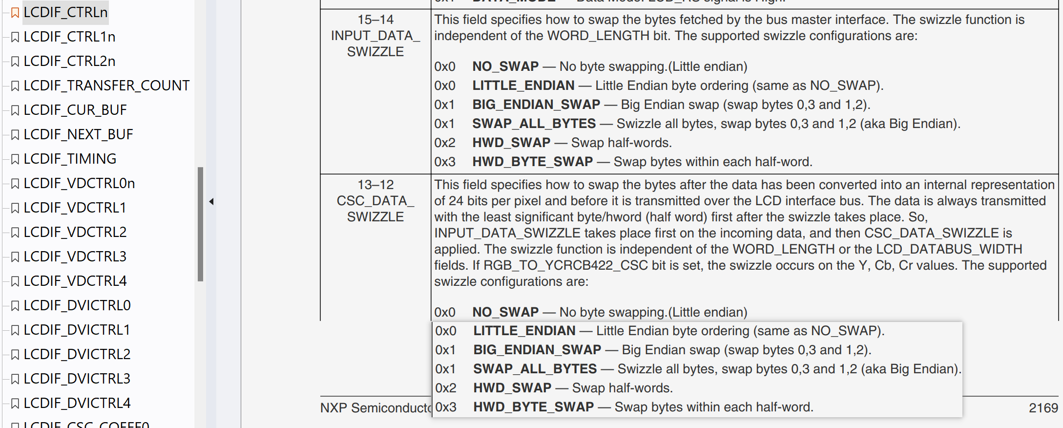
32位字长中有效字节格式
- 0x7:A-RGB888
- 0xF:RGB565

OV5640
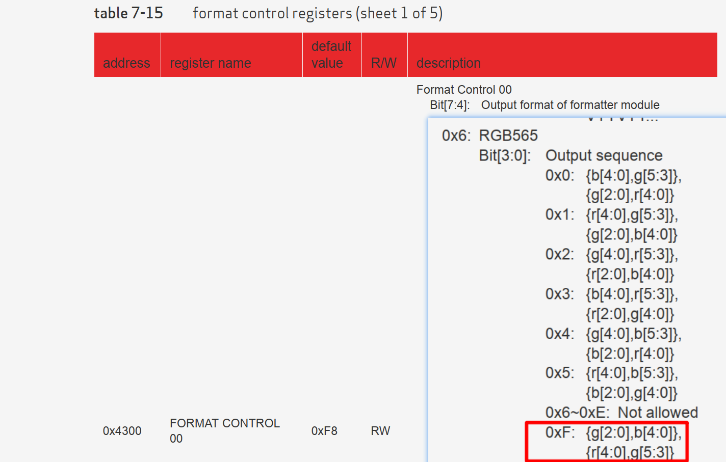
CSI

其他
逻辑分析仪接中断引脚导致引脚一直被拉高
[!WARNING]
在测试GT911时,INT引脚输入模式一直保持高电平,即使加了下拉电阻,在类似的情况下排查下是否是逻辑分析仪产生的干扰。


